The story of installing raspi-config on ubuntu 18.04 and changing the initial settings of GPIO
Introduction
The content of Mr. Kuwano's article in "Chapter 4 Trying to Move an External Circuit by Command Input" of "** Easy ARM Computer I / O with Raspberry Pie **" (Interface Special Edition 2013 CQ Publisher) In the fall of 2020, I confirmed the operation on Ubuntu 18.04 [^ 1]. The content of the article is very easy to understand and the explanation is polite and easy to understand, but since it is premised on using raspbian in the article at the time of 2013, work to disable the SPI setting on GPIO to run on Ubuntu Also, some of the circuit designs introduced need to be changed, and I will write an article about the work contents and notes of the changes to organize my understanding.
[^ 1]: I personally plan to learn ROS in the future, so it's a work that occurred as a result of choosing ubuntu as the OS, which makes it easy to install ROS, so of course,raspbian If it is, even in the latest version, raspi-config is included in the initial settings, so there is no work required to use it.
Experiment environment
- Raspberry Pi 3B+
- Ubuntu 18.04 LTS
Circuit for GPIO test
Below is a link to the reference schematic [^ 2] and a photo of the device actually made [^ 3].
--ONE SEGMENT 7-DIGIT LED TEST BOARD "Circuit Diagram"
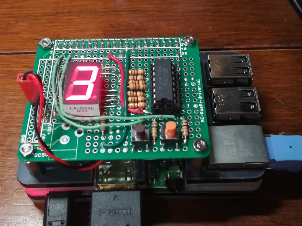 [^ 2]: The circuit of the device actually made is "[ARM device driver programming learned with Raspberry Pi](https://www.socym.co.jp/support/s-940" Satoshi Yoneda 2014 Soshimu " ) ”(Satoshi Yoneda 2014 Soshimu) This is a slightly modified design using the 7-segment LED and 74HC4511 on page 47. The correction points are that the DP terminal is directly connected to GPIO11 via a resistor (510Ω) for control, and a 10k ohm pull-up resistor is used as shown in the "Raspberry Pi I / O" circuit. The only point is that it adds two push switches. The connection to GPIO for switch control uses
 GPIO2 and GPIO3 of J8 GPIO.
[^ 3]: Except for the IC and the universal board, most of the waste materials that I had at home are reused, and the wiring was mistakenly attached and detached many times, so the wiring and making are complicated, but for the time being Is working as instructed.
Confirmation work
First, the GPIO interface in the / sys directory already exists with the default settings.
~$ ls -l /sys/class/gpio/
total 0
--w------- 1 root root 4096 Jan  1  1970 export
lrwxrwxrwx 1 root root    0 Jan  1  1970 gpiochip0 ->
../../devices/platform/soc/3f200000.gpio/gpio/gpiochip0
lrwxrwxrwx 1 root root    0 Jan  1  1970 gpiochip504 -> ../../devices/platform/soc/soc:firmware/soc:firmware:expgpio/gpio/gpiochip504
--w------- 1 root root 4096 Jan  1  1970 unexport
But when I try to create a symlink for the GPIO7 pin, I get scolded as" device or resource is busy and echo write error ".
~$ sudo -s
~# echo 7 >/sys/class/gpio/export
bash: echo: write error: Device or resource busy
By default, the GPIO7 and GPIO8 pins were set for SPI [^ 4].
~# cat /sys/kernel/debug/gpio
gpiochip0: GPIOs 0-53, parent: platform/3f200000.gpio, pinctrl-bcm2835:
gpio-7   (                    |spi0 CS1            ) out hi ACTIVE LOW
gpio-8   (                    |spi0 CS0            ) out hi ACTIVE LOW
gpio-29  (                    |led0                ) out lo
~# exit
[^ 4]: As you can see in the device picture above, the number 3 is automatically displayed when you turn on the power. 3 is displayed in 74HC3411 because GPIO7 and GPIO8 are H from the circuit diagram, so SPI can be used by default when the circuit is connected to GPIO. You can imagine that it is, but it is very convenient if you can check it with a command.
Install raspi-config
I used raspi-config to set the GPIO function. It is a setting change tool dedicated to raspbian, but ubuntu also introduced that it works with the following URL, so I worked according to the procedure introduced.
sudo echo "deb http://archive.raspberrypi.org/debian/ jessie main" >> /etc/apt/sources.list
sudo apt-key adv --keyserver hkp://keyserver.ubuntu.com:80 --recv-keys 7FA3303E
sudo apt-get update
sudo apt-get install raspi-config
sudo mount /dev/mmcblk0p1 /boot
Now you can launch the raspi-config GUI menu screen normally.
~$ sudo rapsi-config
From the rapsi-config top menu screen, select "** 5 Interfacing Options Configure connections to peripherals "> " P4 SPI Enable / Disable automatic loading of SPI kernel module ". After that, if you select " No " in " Would you like the SPI interface to be enabled? ", the message " The SPI interface is disabled " will be displayed and " Ok ". Press "" to return to the top screen, so just save your changes with " Finish **" at the end.
~$ sudo reboot -h now
After rebooting to load the configuration changes, check the GPIO configuration status again.
~# cat /sys/kernel/debug/gpio
gpiochip0: GPIOs 0-53, parent: platform/3f200000.gpio, pinctrl-bcm2835:
gpio-29  (                    |led0                ) out lo
gpiochip1: GPIOs 504-511, parent: platform/soc:firmware:expgpio, raspberrypi-exp-gpio, can sleep:
gpio-506 (                    |led1                ) out lo ACTIVE LOW
If GPIO7 and 8 disappear from the list, you are successful. If that doesn't work, it's possible that your raspi-config changes haven't been saved.
reference
The purpose of this work is to build an execution environment for the circuit test of the device for learning the GPIO device driver that I made. In other words, the final check was to actually run the following shell script code and check for wiring mistakes on the circuit.
There was no error on the command line, and even in the actual test, the number from 0 to 9 was displayed on the 7-segment LED after the dot flashed twice, and the dot flashed twice before ending.
When the push button is open, 1 is displayed on the console screen, and when the button is pressed, 0 is displayed.
The GPIO number layout has changed slightly since the time of "I / O with Raspberry Pi". In this experimental circuit, the physical pin positions of the push switch are the same as the conventional numbers 3 and 5, so the GPIO number is changed from the combination of " 0 and 1" to " 2 ". It is changed programmatically to the combination of 3".
gpio_sh
echo gpio export pin seting ...
echo 2 > /sys/class/gpio/export
echo 3 > /sys/class/gpio/export
echo 7 > /sys/class/gpio/export
echo 8 > /sys/class/gpio/export
echo 9 > /sys/class/gpio/export
echo 10 > /sys/class/gpio/export
echo 11 > /sys/class/gpio/export
echo gpio pin direction seting ...
echo in > /sys/class/gpio/gpio2/direction
echo in > /sys/class/gpio/gpio3/direction
echo out > /sys/class/gpio/gpio7/direction
echo out > /sys/class/gpio/gpio8/direction
echo out > /sys/class/gpio/gpio9/direction
echo out > /sys/class/gpio/gpio10/direction
echo out > /sys/class/gpio/gpio11/direction
echo gpio test start...
echo 1 > /sys/class/gpio/gpio7/value
echo 1 > /sys/class/gpio/gpio8/value
echo 0 > /sys/class/gpio/gpio9/value
echo 1 > /sys/class/gpio/gpio10/value
echo 1 > /sys/class/gpio/gpio11/value
echo 1 > /sys/class/gpio/gpio11/value
sleep 1
echo 0 > /sys/class/gpio/gpio11/value
sleep 1
echo 1 > /sys/class/gpio/gpio11/value
sleep 1
echo 0 > /sys/class/gpio/gpio11/value
sleep 1
echo 0 > /sys/class/gpio/gpio7/value
echo 0 > /sys/class/gpio/gpio8/value
echo 0 > /sys/class/gpio/gpio9/value
echo 0 > /sys/class/gpio/gpio10/value
echo 0
sleep 1
echo 1 > /sys/class/gpio/gpio7/value
echo 0 > /sys/class/gpio/gpio8/value
echo 0 > /sys/class/gpio/gpio9/value
echo 0 > /sys/class/gpio/gpio10/value
echo 1
sleep 1
echo 0 > /sys/class/gpio/gpio7/value
echo 1 > /sys/class/gpio/gpio8/value
echo 0 > /sys/class/gpio/gpio9/value
echo 0 > /sys/class/gpio/gpio10/value
echo 2
sleep 1
echo 1 > /sys/class/gpio/gpio7/value
echo 1 > /sys/class/gpio/gpio8/value
echo 0 > /sys/class/gpio/gpio9/value
echo 0 > /sys/class/gpio/gpio10/value
echo 3
sleep 1
echo 0 > /sys/class/gpio/gpio7/value
echo 0 > /sys/class/gpio/gpio8/value
echo 1 > /sys/class/gpio/gpio9/value
echo 0 > /sys/class/gpio/gpio10/value
echo 4
sleep 1
echo 1 > /sys/class/gpio/gpio7/value
echo 0 > /sys/class/gpio/gpio8/value
echo 1 > /sys/class/gpio/gpio9/value
echo 0 > /sys/class/gpio/gpio10/value
echo 5
sleep 1
echo 0 > /sys/class/gpio/gpio7/value
echo 1 > /sys/class/gpio/gpio8/value
echo 1 > /sys/class/gpio/gpio9/value
echo 0 > /sys/class/gpio/gpio10/value
echo 6
sleep 1
echo 1 > /sys/class/gpio/gpio7/value
echo 1 > /sys/class/gpio/gpio8/value
echo 1 > /sys/class/gpio/gpio9/value
echo 0 > /sys/class/gpio/gpio10/value
echo 7
sleep 1
echo 0 > /sys/class/gpio/gpio7/value
echo 0 > /sys/class/gpio/gpio8/value
echo 0 > /sys/class/gpio/gpio9/value
echo 1 > /sys/class/gpio/gpio10/value
echo 8
sleep 1
echo 1 > /sys/class/gpio/gpio7/value
echo 0 > /sys/class/gpio/gpio8/value
echo 0 > /sys/class/gpio/gpio9/value
echo 1 > /sys/class/gpio/gpio10/value
echo 9
sleep 1
echo 0 > /sys/class/gpio/gpio7/value
echo 1 > /sys/class/gpio/gpio8/value
echo 0 > /sys/class/gpio/gpio9/value
echo 1 > /sys/class/gpio/gpio10/value
echo 1 > /sys/class/gpio/gpio11/value
echo dot
sleep 1
echo 0 > /sys/class/gpio/gpio11/value
sleep 1
echo 1 > /sys/class/gpio/gpio11/value
sleep 1
echo 0 > /sys/class/gpio/gpio11/value
sleep 1
echo 1 > /sys/class/gpio/gpio11/value
cat /sys/class/gpio/gpio2/value
cat /sys/class/gpio/gpio3/value
echo test exiting...
echo 2 > /sys/class/gpio/unexport
echo 3 > /sys/class/gpio/unexport
echo 7 > /sys/class/gpio/unexport
echo 8 > /sys/class/gpio/unexport
echo 9 > /sys/class/gpio/unexport
echo 10 > /sys/class/gpio/unexport
echo 11 > /sys/class/gpio/unexport
echo end
in conclusion
In preparation for the experiment of creating a device driver, I introduced raspi-config to check the operation as simple as possible. In the / sys / kernel / debug / gpio file, gpiochip0: GPIOs 0-53, parent: platform / 3f200000.gpio, pinctrl-bcm2835 is written, and the SOC GPIO address is from 3f200000. Knowing that this is also mentioned here, it's a simple experiment, but Linux has become even more familiar.
Next, I would like to experiment with how to use the GPIO device driver in C language and how to hit the register directly.
Recommended Posts