[C, C ++, Python, JavaScript] L Chika with Edison
If it is an embedded er, start with L Chika.
program
Introduction of MRAA library
To control Edison's IO, Intel provides an abstraction library called MRAA. Source code is here. This library is already installed immediately after purchase or when you write a binary issued by Intel, and you can use it without installing it. If you installed Linux yourself, such as ubilinux, ** first install the latest version of swig from GitHub, ** then mraa Please install.
(\ # Is a command to be executed with administrator privileges) \ # opkg install git cmake # For Yocto Linux \ # apt-get install git cmake autoconf byacc yodl # For Debian $ git clone https://github.com/swig/swig.git $ cd swig $ ./autogen.sh $ ./configure $ make # make install $ cd ../../
$ git clone https://github.com/intel-iot-devkit/mraa.git $ cd mraa $ mkdir build $ cd build $ cmake -DBUILDSWIGNODE=OFF .. $ make # make install
L Chika in C language
The explanation of API is here. The sample is here.
led_c.c
#include <stdio.h>
#include <unistd.h>
#include <mraa.h>

int main(int argc, char *argv[])
{
	mraa_result_t ret;

	//MRAA initialization process (hardware identification)
	mraa_init();

	//MRAA version output
	fprintf(stdout, "Hello mraa.\nVersion: %s\n", mraa_get_version());

	//MRAA port 20(=Breakout board J18-7 pin)Initialization
	mraa_gpio_context gpio;
	gpio = mraa_gpio_init(20);
	if(gpio == NULL){
		return 1;
	}

	//Set port to output
	ret = mraa_gpio_dir(gpio, MRAA_GPIO_OUT);
	if(ret != MRAA_SUCCESS){
		return 1;
	}

	int i;
	for(i=0;i<10;i++){
		//1 on port(H voltage)Output
		mraa_gpio_write(gpio, 1);
		usleep(1000*1000);

		//0 on port(L voltage)Output
		mraa_gpio_write(gpio, 0);
		usleep(1000*1000);
	}

	//Set port to input
	mraa_gpio_dir(gpio, MRAA_GPIO_IN);

	//MRAA termination process
	mraa_deinit();

	return ret;
}
Build this with the following Makefile.
Makefile
CC = g++
MRAALIBS = -lmraa

.PHONY: all clean led_c led_cpp

all: led_c led_cpp

clean:
	rm -f ./*.o
	rm -f led_c led_cpp

led_c: led_c.o
	$(CC) -O4 $(MRAALIBS) -o $@ $^

led_cpp: led_cpp.o
	$(CC) -O4 $(MRAALIBS) -o $@ $^

%.o: %.c
	$(CC) -Wall -g -c $<
Executing ** make ** will generate an executable file called led_c.
# ./led_c Execute with. (Requires administrator authority)
L Chika in C ++
The explanation of API is here. The sample is here. What we are doing inside is almost the same as that of C language.
led_cpp.cpp
#include <stdio.h>
#include <unistd.h>
#include <mraa/gpio.hpp>
#include <mraa/common.hpp>

int main(int argc, char *argv[])
{
	mraa_result_t ret;

	fprintf(stdout, "Hello mraa.\nVersion: %s\n", mraa_get_version());

	mraa::Gpio *gpio = new mraa::Gpio(20);
	if(gpio == NULL){
		return MRAA_ERROR_UNSPECIFIED;
	}

	ret = gpio->dir(mraa::DIR_OUT);
	if(ret != MRAA_SUCCESS){
		mraa::printError(ret);
		return 1;
	}

	for(int i=0;i<5;i++){
		gpio->write(1);
		usleep(1000*1000);

		gpio->write(0);
		usleep(1000*1000);
	}

	gpio->dir(mraa::DIR_IN);

	delete gpio;

	return ret;
}
Makefile is the same as that of C language. An executable file called led_cpp is generated.
# ./led_cpp Execute with. (Requires administrator authority)
L Chika in Python
The sample is here. What you are doing inside is almost the same as that of C / C ++.
led_py.py
#!/usr/bin/env python
# -*- coding:utf-8 -*-

import mraa
import time

print("Hello mraa\nVersion: %s" % mraa.getVersion())

gpio = mraa.Gpio(20)
gpio.dir(mraa.DIR_OUT)

for i in range(5):
	gpio.write(1)
	time.sleep(1)

	gpio.write(0)
	time.sleep(1)

gpio.dir(mraa.DIR_IN)
After creating the file, $ chmod +x ./led_py.py
Then, give the execution authority.
# ./led_py.py You can do it with.
L Chika with JavaScript
The sample is here. What you are doing inside is almost the same as that of C / C ++ / Python.
led_js.js
var m = require("mraa");
console.log("Hello mraa.\nVersion: " + m.getVersion());

var gpio = new m.Gpio(20);
gpio.dir(m.DIR_OUT);

var state = true;
var counter = 20;

periodicActivity();

function periodicActivity(){
        gpio.write(state?1:0);
        state = !state;
        if(counter--)
                setTimeout(periodicActivity, 1000)
}
# node ./led_js.js You can do it with.
circuit

Edison's GND pin (J19-3) seems to be connected to the inner layer GND, so it is very difficult to solder. It is recommended to use a cooperative soldering iron of 30 [W] or higher.
Experiment
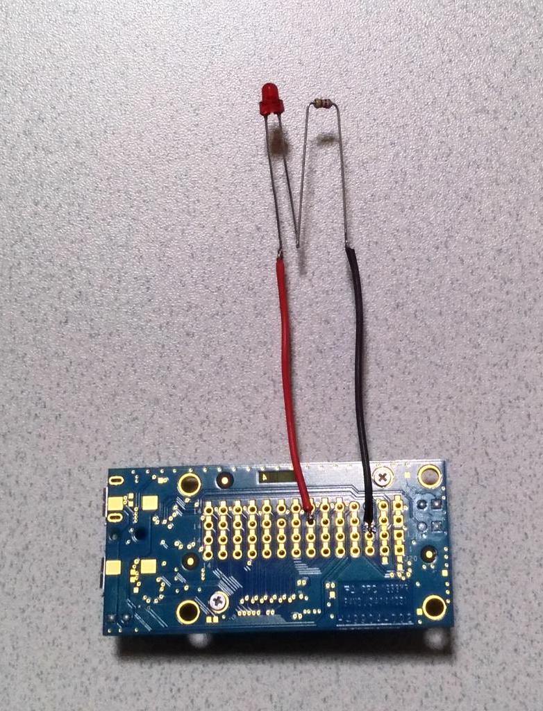
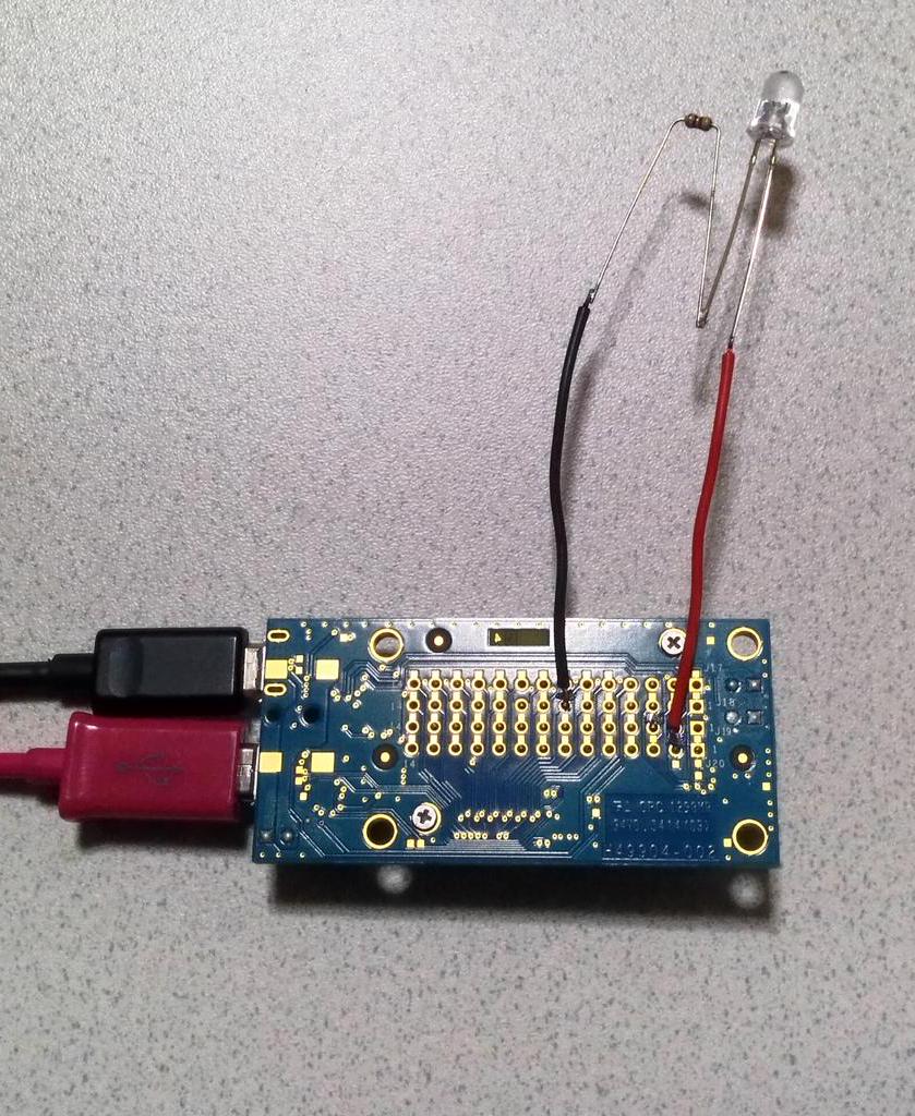
Now, let's actually wire and experiment. For clarity, I soldered the leads directly to the Breakout board (cut out). When conducting a follow-up experiment, it is dangerous, so please solder it properly! !!

Now, when I run the program I mentioned earlier ...
that? It's kind of dark ...
That should be it, Edison can only output a signal with a voltage level of 1.8 [V]. LEDs of colors such as red and green light up dimly because the forward effect voltage (VF) is low, but blue and white LEDs cannot be driven very much. The following video is the one I actually experimented with.
Oh, I'm in trouble.
Circuit redo
If you can only output 1.8 [V] with H voltage, devise a circuit. The previous circuit was called Active High, in which current flows to the load (LED in this case) when 1 is output to the port, but this is called Active Low, and when 0 is output to the port, current flows to the load. Change to a circuit that flows.

In this way, while outputting 1 to the port, the LED will receive 1.5 [V] of 3.3-1.8, and if this is lower than the forward voltage of the LED, the LED will hardly illuminate. Then, when 0 is output to the port, a voltage of 3.3 [V] is applied to the LED, and the LED lights up.

The state of the actual experiment is as follows.
Summary
- Use MRAA library to turn port ON / OFF in Edison,
- The MRAA library has an API that can be hit from C / C ++ / Python / JavaScript.
- The voltage that can be output from the Edison pin is 1.8 [V].
- With Active High, LED drive is difficult, but with Active Low, it can be managed.
Recommended Posts