Scaling and translation with JavaFX Canvas (Revenge)
This article is the 12th day of JavaFX Advent Calendar 2016. Yesterday is @ skrb's Scene Builder 3 small stories. Tomorrow is @ sk44_.
Introduction
JavaFX Canvas has a 2D graphics function that draws vector data and image data such as lines, rectangles, ellipses, and polygons. You can also specify affine transformations to transform 2D drawings such as scaling, translation, rotation, and shear.
Now, let's assume that you can use affine transformation to display 2D data that is larger than the screen by arbitrarily enlarging or reducing it, or scrolling up, down, left, or right to display it. Map display, CAD data display, etc. are examples.
The principle of affine transformation seems to be simple, but it often fits in when I try it, and even two years ago [Affine transformation in Canvas fits a lot (I didn't have enough mathematical sense ...)]( I even wrote a blog called http://d.hatena.ne.jp/torutk/20140415/p1).
At the JJUG CCC 2016 Fall held on the 3rd of this month, we announced the content of drawing map data (world coastline data) with JavaFX Canvas under the title "The world is not a square-drawing a map with JavaFX". In the map display sample program prepared at this time, enlargement / reduction / scrolling is performed using affine transformation. However, there was a problem that the position of the displayed map would shift when scaling up or down. Unfortunately, it could not be resolved by the day of the announcement.
Therefore, as a revenge, when enlarging / reducing the display, I decided to re-study the affine transformation from the basics and organize it so that the center of the data displayed on the screen does not shift.
Execution environment of this article
This article is written for the purpose of investigating and understanding JavaFX affine transformations, so there is no sample program. To easily check the operation of Affine conversion, I am using the command line environment jshell that will be included in JDK 9, which will be released next year.
On Windows 10 64bit environment, I put Java SE Development Kit 9 Early Access version and use the shell command. At the time of writing, it is the JDK 9 Build 148 version.
Data coordinate system and screen coordinate system
Data shapes are generally defined in a Cartesian coordinate system. This Cartesian coordinate system represents the right-handed system, that is, the positive direction of the x-axis rotated 90 degrees counterclockwise as the positive direction of the y-axis.
On the other hand, JavaFX screen coordinates are also defined in the Cartesian coordinate system, which represents the left-handed system, that is, the direction in which the positive direction of the x-axis is rotated 90 degrees clockwise as the positive direction of the y-axis. ..

Therefore, if the coordinates of the data are displayed on the screen as they are, they will be upside down.
If you display the map data without converting it ...
Map data is generally defined in latitude and longitude coordinates. Expressing this on the y-axis for latitude and the x-axis for longitude gives the following data.
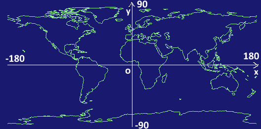
If this map data is displayed on the screen without any coordinate conversion, the display will be as follows.

The range from the first quadrant (0,0) to (180,90) of the coordinate system of the map data is displayed upside down.
Therefore, we will introduce coordinate conversion from the data coordinate system to the screen coordinate system so that the data can be displayed by arbitrarily enlarging / reducing / translating / rotating it. The coordinate transformation used at that time is the affine transformation.
Conversion from data coordinate system to screen coordinate system by affine transformation
Let the data coordinate system be the xy coordinate system and the screen coordinate system be the x'y' coordinate system. Assuming that the points on the xy coordinate system are (x, y) and the points on the x'y'coordinate system are (x', y'), the coordinate conversion from the data coordinate system to the screen coordinate system is (x, y). ) Is the input and (x', y') is the output.
x' = ax + by + t_x\\
y' = cx + dy + t_y
When this conversion formula is reexpressed as a vector for coordinates and a matrix for conversion
\begin{pmatrix}
x'\\
y'\\
1
\end{pmatrix}
= \begin{pmatrix}
a & b & t_x\\
c & d & t_y\\
0 & 0 & 1
\end{pmatrix}
\begin{pmatrix}
x\\
y\\
1
\end{pmatrix}
It will be. This matrix becomes the Affine transformation matrix. (In the case of 2D) Due to the handling of calculation, it is calculated (homogeneous coordinates) with a cubic vector / matrix.
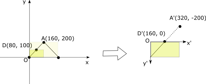
Coordinate transformation (1): Identity transformation
x' = x\\
y' = y\\
If you apply the conversion (that is, do not convert anything), the display will be upside down. Expressed in affine transformation, it is as follows.
\begin{pmatrix}
x'\\y\\1'
\end{pmatrix}=
\begin{pmatrix}
1 & 0 & 0\\
0 & 1 & 0\\
0 & 0 & 1
\end{pmatrix}
\begin{pmatrix}
x\\y\\1
\end{pmatrix}
With this conversion (no conversion), the data will be displayed on the screen as follows.

The yellow rectangle is the screen drawing area. Points A, B, and C are converted (no conversion) to A', B', C'as follows.
\begin{align*}
(A'_x, A'_y) &= (A_x, A_y) = (160, 200)\\
(B'_x, B'_y) &= (B_x, B_y) = (320, 0)\\
(C'_x, C'_y) &= (C_x, C_y) = (160, -200)
\end{align*}
This affine transformation is created with the following code.
Affine affine = new Affine();
Experimenting with Affine in the jshell environment of JDK 9
Put the environment variable PATH in JDK 9. Run jshell.
C:\>java -version
java version "9-ea"
Java(TM) SE Runtime Environment (build 9-ea+148)
Java HotSpot(TM) 64-Bit Server VM (build 9-ea+148, mixed mode)

C:\>jshell
|Welcome to JShell--Version 9-ea
|For an overview, type:: /help intro
|
jshell>
Generates an Affine transformation (identity transformation).
jshell> import javafx.scene.transform.Affine

jshell> Affine affine = new Affine()
affine ==> Affine [
        1.0, 0.0, 0.0, 0.0
        0.0, 1.0, 0.0, 0.0
        0.0, 0.0, 1.0, 0.0
]
The jshell environment is convenient because it displays the contents of the defined variables. However, it is displayed in 3 rows and 4 columns. This is because JavaFX comes standard with 3D graphics so it can handle 3D coordinate transformations.
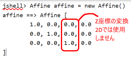
When dealing with 2D affine transformations, don't worry about the third column, as shown above.
Next, let's create one point in the data coordinate system and transform it with this Affine.
jshell> import javafx.geometry.Point2D

jshell> Point2D dataA = new Point2D(160, 200)
dataA ==> Point2D [x = 160.0, y = 200.0]

jshell> affine.transform(dataA)
$5 ==> Point2D [x = 160.0, y = 200.0]

jshell>
Coordinates with the same values as the original coordinates (160,200) were obtained as a result of this Affine transformation.
Coordinate conversion (2): Elimination of upside down
Since the y-axis is reversed, we think that we can simply reverse the sign of the y-coordinate and introduce the following coordinate transformation.
\begin{align*}
x' &= x\\
y' &= -y\\
\end{align*}
Expressed in affine transformation, it is as follows.
\begin{pmatrix}
x'\\y'\\1
\end{pmatrix}=
\begin{pmatrix}
1 & 0 & 0\\
0 & -1 & 0\\
0 & 0 & 1
\end{pmatrix}
\begin{pmatrix}
x\\y\\1
\end{pmatrix}

Points A, B, and C are converted to A', B', C'as follows.
\begin{align*}
(A'_x, A'_y) &= (A_x, -A_y) = (160, -200)\\
(B'_x, B'_y) &= (B_x, -B_y) = (320, 0)\\
(C'_x, C'_y) &= (C_x, -C_y) = (160, 200)
\end{align*}
The data display is no longer upside down, but the data display area is off the display area in (Part 1) (opposite the X-axis).
This affine transformation is created with the following code.
Affine affine = new Affine(1, 0, 0, 0, -1, 0);
Experimenting with Affine in the jshell environment of JDK 9
jshell> affine = new Affine(1, 0, 0, 0, -1, 0)
affine ==> Affine [
        1.0, 0.0, 0.0, 0.0
        0.0, -1.0, 0.0, 0.0
        0.0, 0.0, 1.0, 0.0
]

jshell> affine.transform(dataA)
$9 ==> Point2D [x = 160.0, y = -200.0]

jshell>
Point A has been converted from (160, 200) to (160, -200). Similarly, let's see the conversion results for points B and C.
jshell> Point2D dataB = new Point2D(320, 0)
dataB ==> Point2D [x = 320.0, y = 0.0]

jshell> affine.transform(dataB)
$12 ==> Point2D [x = 320.0, y = -0.0]

jshell> Point2D dataC = new Point2D(160, -200)
dataC ==> Point2D [x = 160.0, y = -200.0]

jshell> affine.transform(dataC)
$13 ==> Point2D [x = 160.0, y = 200.0]

jshell>
Point B has been converted from (320, 0) to (320, -0) (coordinate values unchanged). Point C has been converted from (160, -200) to (160, 200).
Coordinate transformation (3): Translation of origin
The origin of the data coordinate system is the lower left corner of the area you want to draw, but the origin of the screen coordinate system is the upper left corner of the area to be drawn. Therefore, move the origin of the data coordinate system in parallel to the origin of the screen coordinate system to match the area you want to draw.
In this case, the translation is the height of the drawing area in the y-axis direction. Assuming that the height of the drawing area is h, the conversion formula is as follows.
\begin{align*}
x' &= x\\
y' &= -(y - h) = -y + h\\
\end{align*}
Expressed in affine transformation, it is as follows.
\begin{pmatrix}
x'\\y'\\1
\end{pmatrix}=
\begin{pmatrix}
1 & 0 & 0\\
0 & -1 & h\\
0 & 0 & 1
\end{pmatrix}
\begin{pmatrix}
x\\y\\1
\end{pmatrix}
The figure and each coordinate when the height h is 200 are as follows.

\begin{align*}
(A'_x, A'_y) &= (A_x, -A_y + 200) = (160, 0)\\
(B'_x, B'_y) &= (B_x, -B_y + 200) = (320, 200)\\
(C'_x, C'_y) &= (C_x, -C_y + 200) = (160, 0)
\end{align*}
This affine transformation is created with the following code.
Affine affine = new Affine(1, 0, 0, 0, -1, 200);
Experimenting with Affine in the jshell environment of JDK 9
jshell> affine = new Affine(1, 0, 0, 0, -1, 200)
affine ==> Affine [
        1.0, 0.0, 0.0, 0.0
        0.0, -1.0, 0.0, 200.0
        0.0, 0.0, 1.0, 0.0
]

jshell> affine.transform(dataA)
$19 ==> Point2D [x = 160.0, y = 0.0]

jshell> affine.transform(dataB)
$20 ==> Point2D [x = 320.0, y = 200.0]

jshell> affine.transform(dataC)
$21 ==> Point2D [x = 160.0, y = 400.0]

jshell>
Point A has been converted from (160, 200) to (160, 0). Point B has been converted from (320, 0) to (320, 200). Point C has been converted from (160, -200) to (160, 400).
Coordinate conversion (4): Move the drawing area
Move the drawing area anywhere in the data coordinate system. Assuming that the coordinates of the upper left corner of the drawing area are (x1, y1), the following equation expresses translation.
\begin{align*}
x' &= x - x_1\\
y' &= -(y - y_1) = -y + y_1
\end{align*}
Expressed in affine transformation, it is as follows.
\begin{pmatrix}
x'\\y'\\1
\end{pmatrix}=
\begin{pmatrix}
1 & 0 & -x_1\\
0 & -1 & y_1\\
0 & 0 & 1
\end{pmatrix}
\begin{pmatrix}
x\\y\\1
\end{pmatrix}
The figure and each coordinate when (x1, y1) is (-280, 500) are as follows.
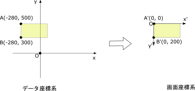
\begin{align*}
(A'_x, A'_y) &= (A_x - (-280), -(A_y - 500))\\
 &= (A_x + 280, -A_y + 500)\\
 &= (0, 0)\\
(B'_x, B'_y) &= (B_x - (-280), -(B_y - 500))\\
 &= (B_x + 280, -B_y + 500)\\
 &= (0, 200)
\end{align*}
This affine transformation is created with the following code.
Affine affine = new Affine(1, 0, 280, 0, -1, 500);
It's a little confusing.
Consider a combination of two coordinate transformations.
- Translation
- Upside down
The affine transformation of translation is expressed by the following determinant.
\begin{pmatrix}
1 & 0 & -x_1\\
0 & 1 & -y_1\\
0 & 0 & 1
\end{pmatrix}
The upside-down affine transformation is expressed by the following determinant.
\begin{pmatrix}
1 & 0 & 0\\
0 & -1 & 0\\
0 & 0 & 1
\end{pmatrix}
First, translate and then flip it upside down. In this case, when joining matrices, write the one to be applied first on the right side.
\begin{pmatrix}
1 & 0 & 0\\
0 & -1 & 0\\
0 & 0 & 1
\end{pmatrix}
\begin{pmatrix}
1 & 0 & -x_1\\
0 & 1 & -y_1\\
0 & 0 & 1
\end{pmatrix}=
\begin{pmatrix}
1 & 0 & -x_1\\
0 & -1 & y_1\\
0 & 0 & 1
\end{pmatrix}
Experimenting with Affine in the jshell environment of JDK 9
Combine two Affines.
jshell> Affine affineMove = new Affine(1, 0, -(-280), 0, 1, -500)
affineMove ==> Affine [
        1.0, 0.0, 0.0, 280.0
        0.0, 1.0, 0.0, -500.0
        0.0, 0.0, 1.0, 0.0
]

jshell> Affine affineReverse = new Affine(1, 0, 0, 0, -1, 0)
affineReverse ==> Affine [
        1.0, 0.0, 0.0, 0.0
        0.0, -1.0, 0.0, 0.0
        0.0, 0.0, 1.0, 0.0
]

jshell> affineReverse.createConcatenation(affineMove)
$35 ==> Affine [
        1.0, 0.0, 0.0, 280.0
        0.0, -1.0, 0.0, 500.0
        0.0, 0.0, 1.0, 0.0
]
Well, it's still hard to understand ...
Now, let's perform coordinate transformation.
jshell> affine = new Affine(1, 0, 280, 0, -1, 500)
affine ==> Affine [
        1.0, 0.0, 0.0, 280.0
        0.0, -1.0, 0.0, 500.0
        0.0, 0.0, 1.0, 0.0
]

jshell> Point2D dataJ = new Point2D(-280, 500)
dataJ ==> Point2D [x = -280.0, y = 500.0]

jshell> affine.transform(dataJ)
$29 ==> Point2D [x = 0.0, y = 0.0]

jshell> Point2D dataK = new Point2D(-280, 300)
dataK ==> Point2D [x = -280.0, y = 300.0]

jshell> affine.transform(dataK)
$30 ==> Point2D [x = 0.0, y = 200.0]
The data coordinate system (-280, 500) has been converted to the screen coordinate system (0, 0). The data coordinate system (-280, 300) has been converted to the screen coordinate system (0, 200).
Coordinate transformation (5): Scaling and translation
Enlarges or reduces the size of the drawing area of the data coordinate system to any size. Assuming that the scaling factor is S and the coordinates of the upper left corner of the drawing area on the data coordinate system are (x1, y1), the following formula expresses scaling and translation.
\begin{align*}
x' &= s(x - x_1) = sx - sx_1\\
y' &= -s(y - y_1) = -sy + sy_1
\end{align*}
Expressed in affine transformation, it is as follows.
\begin{pmatrix}
x'\\y'\\1
\end{pmatrix}=
\begin{pmatrix}
s & 0 & -sx_1\\
0 & -s & sy_1\\
0 & 0 & 1
\end{pmatrix}
\begin{pmatrix}
x\\y\\1
\end{pmatrix}
In case of magnification 2 and translation (0, 100)
Here, let's look at the display area of the data coordinate system and the conversion to the screen coordinate system when the enlargement ratio is 2 and the translation amount is (0,100).

Since the magnification is doubled, a range of 160x100 in the data coordinate system is drawn in the screen coordinate system 320x200.
\begin{align*}
(A'_x, A'_y) &= (2A_x +2.0, -2A_y +2.100)\\
 &= (0, 0)\\
(B'_x, B'_y) &= (2B_x +2.0, -2B_y +2.100)\\
 &= (320, 0)\\
(C'_x, C'_y) &= (2C_x +2.0, -2C_y +2.100)\\
 &= (320, 200)
\end{align*}
The content of the data looks like the following figure.
This affine transformation is created with the following code.
Affine affine = new Affine(2, 0, 0, 0, -2, 200);
Experimenting with Affine in the jshell environment of JDK 9
jshell> affine = new Affine(2, 0, 0, 0, -2, 200)
affine ==> Affine [
        2.0, 0.0, 0.0, 0.0
        0.0, -2.0, 0.0, 200.0
        0.0, 0.0, 1.0, 0.0
]

jshell> dataA = new Point2D(0, 100)
dataA ==> Point2D [x = 0.0, y = 100.0]

jshell> affine.transform(dataA)
$38 ==> Point2D [x = 0.0, y = 0.0]

jshell> dataB = new Point2D(160, 100)
dataB ==> Point2D [x = 160.0, y = 100.0]

jshell> affine.transform(dataB)
$40 ==> Point2D [x = 320.0, y = 0.0]

jshell> dataC = new Point2D(160, 0)
dataC ==> Point2D [x = 160.0, y = 0.0]

jshell> affine.transform(dataC)
$42 ==> Point2D [x = 320.0, y = 200.0]
The data coordinate system (0, 100) has been converted to the screen coordinate system (0, 0). The data coordinate system (160, 100) has been converted to the screen coordinate system (320, 0). The data coordinate system (160, 0) has been converted to the screen coordinate system (320, 200).
Example with magnification of 0.5 and translation (100, 1000)
The figure below shows the conversion when the magnification is 0.5 and the translation amount is (100,1000).
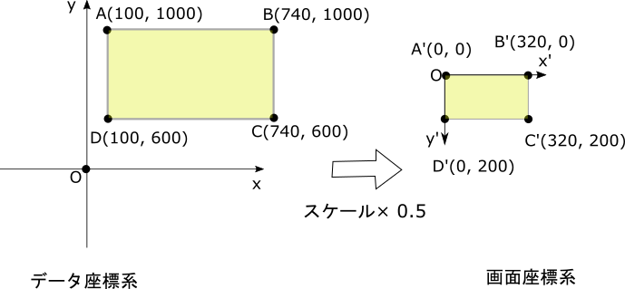
The matrix of the affine transformation at this time is as follows.
\begin{pmatrix}
0.5 & 0 & -50\\
0 & -0.5 & 500\\
0 & 0 & 1
\end{pmatrix}
Experimenting with Affine in the jshell environment of JDK 9
jshell> Affine affine = new Affine(0.5, 0, -50, 0, -0.5, 500)
affine ==> Affine [
        0.5, 0.0, 0.0, -50.0
        0.0, -0.5, 0.0, 500.0
        0.0, 0.0, 1.0, 0.0
]

jshell> affine.transform(100, 1000)
$4 ==> Point2D [x = 0.0, y = 0.0]

jshell> affine.transform(740, 1000)
$5 ==> Point2D [x = 320.0, y = 0.0]

jshell> affine.transform(740, 600)
$6 ==> Point2D [x = 320.0, y = 200.0]

jshell> affine.transform(100, 600)
$7 ==> Point2D [x = 0.0, y = 200.0]

jshell>
This time, I tried to input the x-coordinate value and y-coordinate value directly instead of the Point2D instance as the input of conversion.
The data coordinate system (100, 1000) has been converted to the screen coordinate system (0, 0). The data coordinate system (740, 1000) has been converted to the screen coordinate system (320, 0). The data coordinate system (740, 600) has been converted to the screen coordinate system (320, 200). The data coordinate system (100, 600) has been converted to the screen coordinate system (0, 200).
Coordinate conversion (6): Scaling at the center of the screen
In the enlargement / reduction in the coordinate conversion so far, the upper left of the screen is the base point. Next, let's take a look at the display of a Canvas sample program that implements the coordinate transformation so far. If you expand from display (1) to display (3), you can see that the display is based on the upper left corner.
-
Display (1)

-
Display (2)

-
Display (3)

However, as an intuitive operation, I would like you to zoom in and out with the center of the screen as the base point.
Therefore, this time, we will add a translation that moves the coordinates of the upper left corner of the screen to the center of the screen in the screen coordinate system.
First, the coordinate transformation formula used in "Coordinate transformation (5): Scaling and translation" is listed again.
\begin{align*}
x' &= sx - sx_1 \\
y' &= -sy + sy_1
\end{align*}
Let w be the width of the screen and h be the height of the screen. The coordinate conversion formula for the operation of translating the upper left corner of the screen to the center of the screen is as follows.
\begin{align*}
x'' &= x' + \frac{w}{2}\\
y'' &= y' + \frac{h}{2}
\end{align*}
The coordinate conversion formula that added the operation to translate the upper left corner of the screen to the center of the screen is as follows.
\begin{align*}
x'' &= sx - sx_1 + \frac{w}{2}\\
y'' &= -sy + sy_1 + \frac{h}{2}
\end{align*}
Since the translation according to the screen size is not affected by the scaling of the data coordinate system, the scaling factor s is not applied as in the above formula.
The figure is shown below.
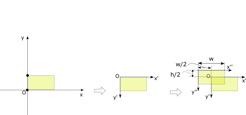
The affine transformation is expressed by the following determinant.
\begin{pmatrix}
s & 0 & -sx_1 + \frac{w}{2}\\
0 & -s & sy_1 + \frac{h}{2}\\
0 & 0 & 1
\end{pmatrix}
Experimenting with Affine in the jshell environment of JDK 9
When the screen size is 320x200, the upper left corner coordinates of the drawing area in the data coordinate system are (200, 500), and the scale is 2.
jshell> affine = new Affine(2, 0, -240, 0, -2, 1100)
affine ==> Affine [
        2.0, 0.0, 0.0, -240.0
        0.0, -2.0, 0.0, 1100.0
        0.0, 0.0, 1.0, 0.0
]

jshell> affine.transform(200, 500)
$12 ==> Point2D [x = 160.0, y = 100.0]
And you can see that the upper left corner (200, 500) of the data coordinate system has been converted to (160, 100) in the screen coordinate system and the screen center.
When the screen size is 320x200, the upper left corner coordinates of the drawing area in the data coordinate system are (200, 500), and the scale is 0.5.
jshell> affine = new Affine(0.5, 0, 60, 0, -0.5, 350)
affine ==> Affine [
        0.5, 0.0, 0.0, 60.0
        0.0, -0.5, 0.0, 350.0
        0.0, 0.0, 1.0, 0.0
]

jshell> affine.transform(200, 500)
$14 ==> Point2D [x = 160.0, y = 100.0]
And you can see that the upper left corner (200, 500) of the data coordinate system has been converted to (160, 100) in the screen coordinate system and the screen center.
Summary
The affine transformations used to display the data defined in the right-handed Cartesian coordinate system on the screen are as follows:
\begin{pmatrix}
s & 0 & -sx_1 + \frac{w}{2}\\
0 & -s & sy_1 + \frac{h}{2}\\
0 & 0 & 1
\end{pmatrix}
However,\\
s is the expansion rate\\
(x_1, y_1)Is the data coordinates displayed in the center of the screen\\
(w, h)Is the width and height of the display size in the screen coordinate system
Reference / related information
The following is a sample program for displaying screens on JavaFX Canvas using this affine transformation and its explanation.
- [Vector drawing and scaling movement operation using JavaFX Canvas](http://www.torutk.com/projects/swe/wiki/JavaFX_Canvas%E3%82%92%E4%BD%BF%E3%81% A3% E3% 81% 9F% E3% 83% 99% E3% 82% AF% E3% 82% BF% E3% 83% BC% E6% 8F% 8F% E7% 94% BB% E3% 81% A8% E6% 8B% A1% E5% A4% A7% E7% B8% AE% E5% B0% 8F% E7% A7% BB% E5% 8B% 95% E6% 93% 8D% E4% BD% 9C)
The presentation slides at JJUG CCC 2016 Fall, which inspired me to write this article, are as follows.
A blog that wrote about working on affine transformation in Canvas in the past
Recommended Posts